

Ruggybuggy
Site Supporter
- Joined
- Apr 7, 2014
- Messages
- 967
- Reaction score
- 3
- Points
- 18
- Location
- Kenora, NW ONT, CANADA
No, there are 3-Positions on those connector housings and theres 3-4 of those plugs that you refer to as "2-Pin". There's also a single 4-Position on the connector housing with only 3 wires installed.
These are the mating connectors, CON-30 cable Assembly and CON-40 cable Assembly that I used for my installation...
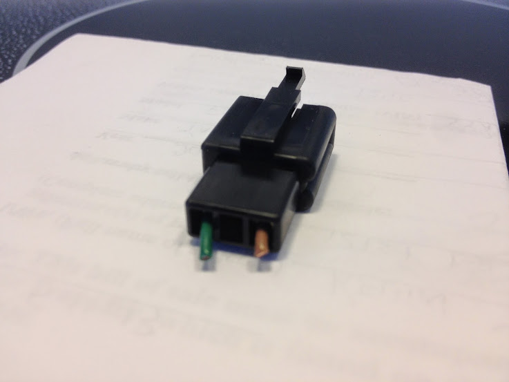
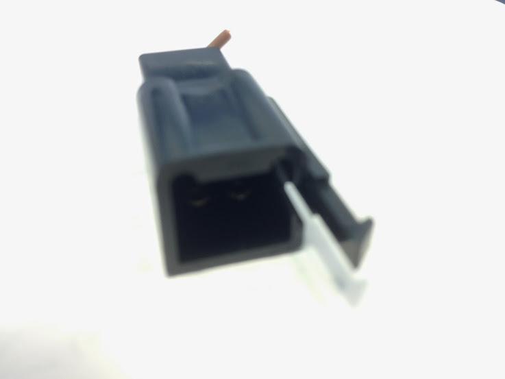
I have three of these connectors. The brown wire is switched 12V with key and the green is ground. These are the actual connectors off the Honda auxiliary harness.

This is the 4 terminal connector that only has three wires installed. This is the actual connector of the Honda auxiliary harness and there is only one of them. The brown wire is switched 12V with the key, the green is ground and the blue wire does nothing because it doesn't mate to any wires in on the Honda 6 way connector.

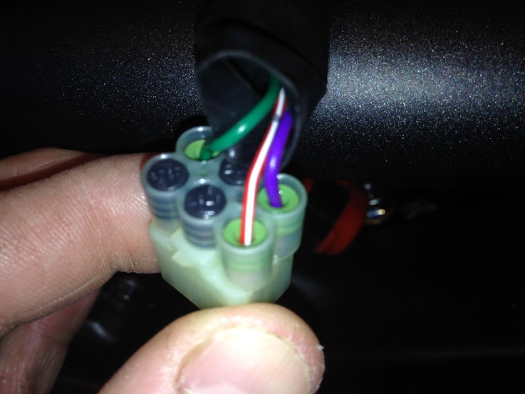
Honda 6 way connector that only has 3 wires. This is the connector that mates with the Honda auxiliary harness. The green wire is a ground wire, the blue wire is a switched 12V with the key in the run position. The red/white wire is a constant 12V and does not mate to any wire in the Honda auxiliary harness.
Attachments
Last edited:

") Good detective work
Good detective work