

Lou Wambsganss
Elite Member
- Joined
- Oct 23, 2013
- Messages
- 279
- Reaction score
- 3
- Points
- 0
- Location
- United States, Dallas, TX
Here is a mod that I've been planning on trying for a while. I am about 6'3" tall, with a 36" inseam and have tried a few things to improve my ergos by spreading things out a little. I have a 1.5" handlebar riser, and have done the Showkey Mod (http://nc700-forum.com/forum/nc700-mods/1574-seat-mod-slope-change.html) on my seat, which raises the height a little (maybe an inch...). The last thing to do was lower the pegs a little. Using Buell pegs is a mod that has been discussed briefly in other threads, but I figure it deserves its own thread for all the details.
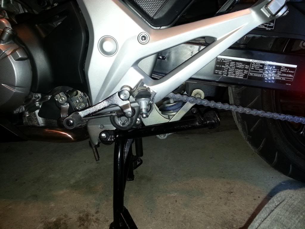
Here is the stock footpeg, for reference.
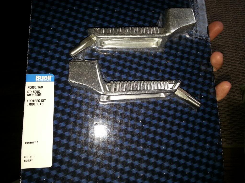
I couldn't easily find the stock Honda footpeg part numbers. The Buell kit I used is the N0006.1AD. These pegs have about a 1" drop from the Hondas.
Here is a quick ref sheet of applicable dimensions. I measured all dimensions in decimal inches using a cheap pipe caliper, so there are a few thousandths plus or minus in all dimensions given. I have included the closest cross to fractional inch and metric measurements.

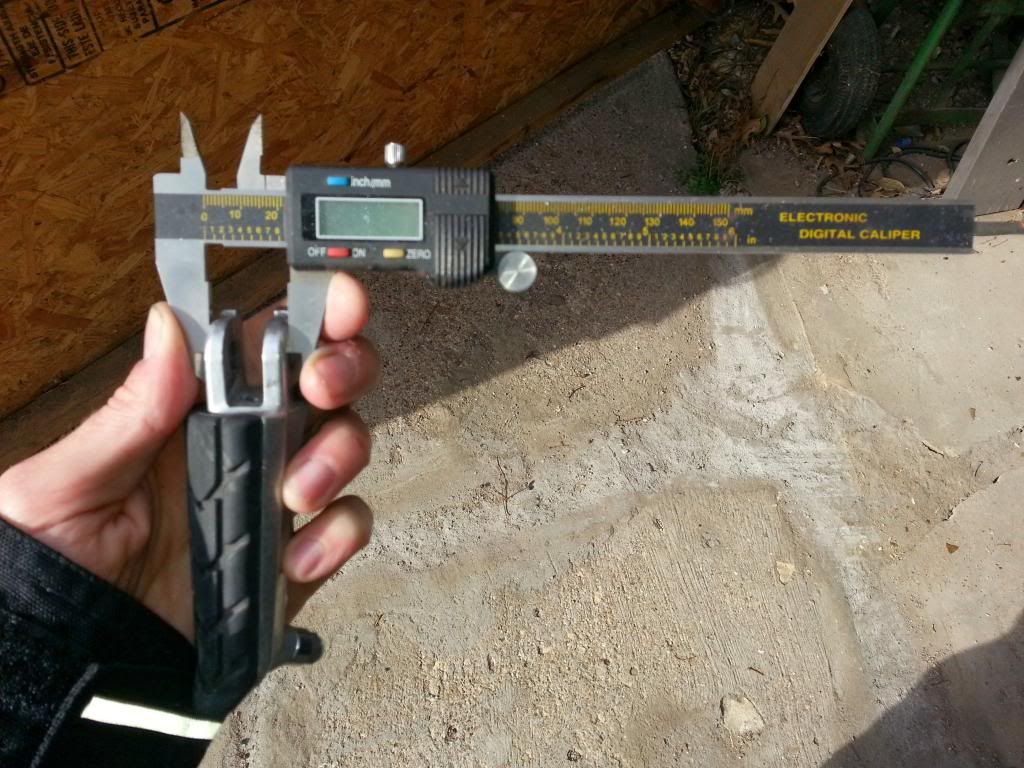
When I say "Yoke Height", what I mean is the distance between the outer surfaces of the peg in the mounting pin area. Here is a pic of the measurement.
Basically, you have two options to get pegs like this to fit. You can ream out the Honda side casting and use a larger pin, or you can install a bushing in the large hole on the Buell pegs to allow the use of the original smaller pin. I wanted to keep the bike parts stock, so that I could go back to the original pegs if I ever wanted to. All of the modification had to stay on the pegs, not the bike. If one wanted to ream the Honda holes to accept a larger pin, it should still work fine. There is plenty of lug wall thickness on the Honda casting flanges and tearout should not be an issue.
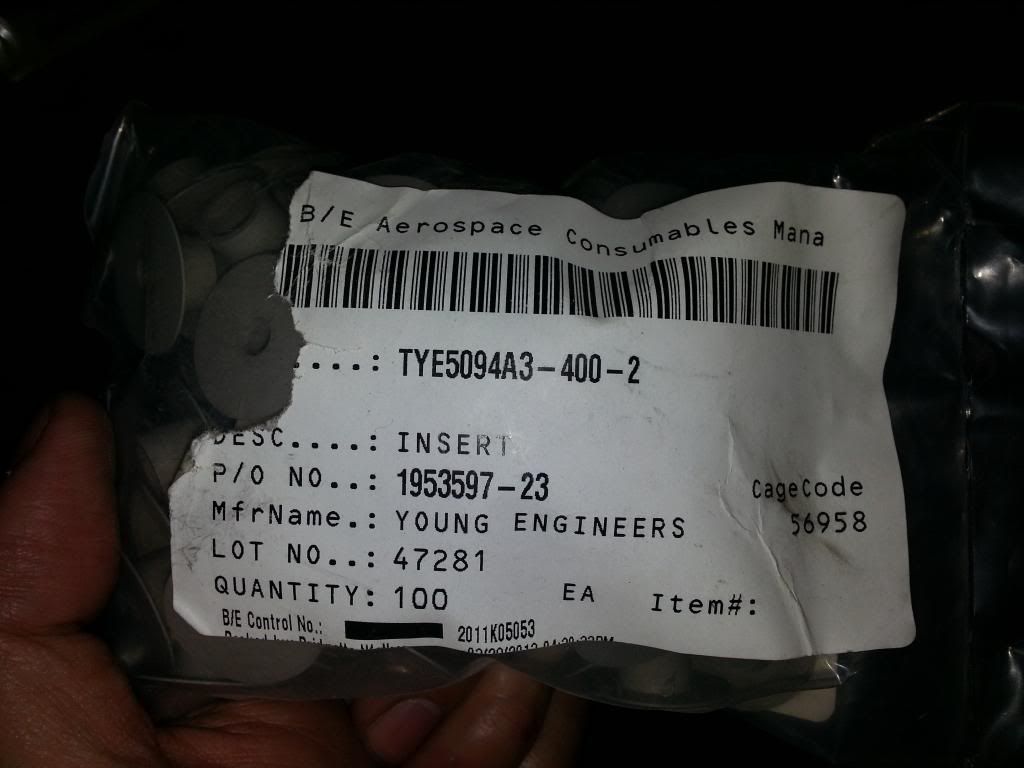
The first thing I did was found some bushings to make up the pin diameter difference. I got extremely lucky here and had some anodized aluminum hat bushings in my tool box. I think they are Boeing floorboard insert bushings. The "tube" section of the bushing is the exact right inner and outer diameter. These bushings are anodized, heat treated aircraft aluminum and will probably outlast the pegs or the Honda casting. Seriously, I can't believe how luck I was to find these. If anyone else wants a set to do a footpeg mod, send me a message, I can probably spare a few.
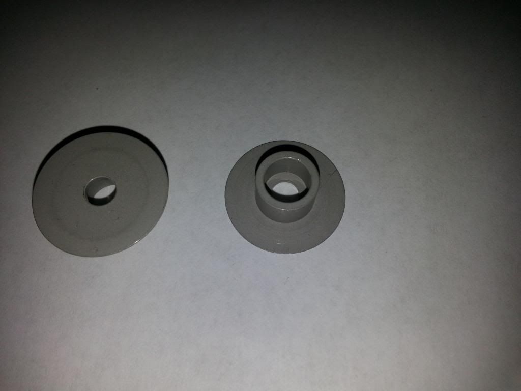
Anyway, the bushings were not quite an exact fit. As you can see, the "hat" end has a smaller diameter hole, which I drilled out with a 5/16" drill bit. This makes the bushing one straight inner diameter of 5/16" all the way through. I also had to trim a little bit off of the hat flange in order to get them to nest in the pegs. The hat is thin and can be trimmed with hand shears, wire cutters, etc.
I installed two bushings in each peg, with the hats on the inside of the peg. The hats prevent the bushings from walking out. You will need some sort of spacer in between them. I used a small piece of copper tube cut to length. Basically, anything to take up the space between the bushings will work here. The peg spring might even retain them on its own.
The bushings are a little taller than they need to be and will protrude from the peg a little. I had to take about 0.090" of metal off the peg yoke flanges anyway, so sanding the bushings down at the same time was not a problem.
Speaking of sanding the yoke flanges, this was the most time consuming part of the project. I didn't want to take off too much metal, so I marked a cut line of the required thickness on the lower flange and started sanding with a die grinder and 3M 2" diameter 120 grit sanding pads. Luckily, the Buell pegs are made out of a cast aluminum that is approximately as hard as a nicely aged cheese.") At least when compared to the structural alloys I'm used to grinding on for aircraft. I would take a pass with the grinder, test fit, grind more, test again, lather, rinse, repeat until they fit. As you get close, the pegs can start to wedge into position. Once the pin will fit through, I would install it and wiggle the peg in position. This would leave a contact mark on the peg, so I knew where the high spots were that needed more sanding.
At least when compared to the structural alloys I'm used to grinding on for aircraft. I would take a pass with the grinder, test fit, grind more, test again, lather, rinse, repeat until they fit. As you get close, the pegs can start to wedge into position. Once the pin will fit through, I would install it and wiggle the peg in position. This would leave a contact mark on the peg, so I knew where the high spots were that needed more sanding.
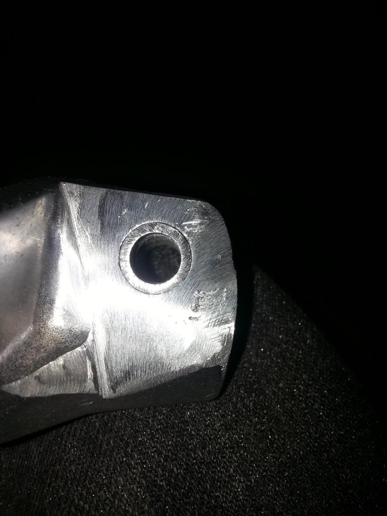
I tried to take almost all of the required metal off of the bottom flange. This flange is under compression when weight is applied to the peg. The top flange in under tension. This is the critical point, so I wanted it to stay basically as strong as Buell designed it to be. The lower flange will not fail, as the compression load is pushing into the meat of the peg casting, rather than pulling against the lug wall on the upper flange.
Once I had the thickness dialed in, I went over the sanded areas with a 3M green Scotch Wheel to polish the surface. It should leave a roughness of about 63 microinches, which is enough to prevent stress cracks from forming in the aluminum on the rough sand marks.
Once the peg will fit between the casting flanges, you will still have to take some material off of the peg flange edges, in order to set the position and allow full spring up travel. It's not much, and the procedure is basically the same. Put the pin through, cycle the peg up and down a few times, and sand away where the impact parks are. After a few tries, it should be good.
I used a No 2 Moly grease on all bushings, pins, and contact surfaces when I permanently installed everything.
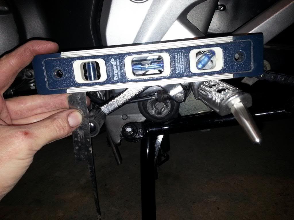
After the new pegs are installed, you should adjust the brake and shifter (as applicable) down to match. I like my controls to be a little over an inch (about 30mm) lower than my pegs. I did notice a little bit of interference between the LH peg and the shift lever. This required a little bit of additional spot grinding on the peg.
I think I might use Plasti-Dip or some sort of coating on the pegs, both for looks and maybe anti-slip.
Overall, I am very happy with this mod. My legs are a little less tight and my knee angle is less acute. It took me about $40 and 4 hours to do all the work, from initial brainstorming to final product. Anyone who wants to follow this procedure should be able to do it in less time, since the trial and error has already been done.
Here is me sitting on a stock NC700x (no mods).

Here is me sitting on my NC700X as it is now (lowered pegs, raised seat, raised handlebar).

Notice the increased knee and hip angles and decreased lean.
Here is the stock footpeg, for reference.
I couldn't easily find the stock Honda footpeg part numbers. The Buell kit I used is the N0006.1AD. These pegs have about a 1" drop from the Hondas.
Here is a quick ref sheet of applicable dimensions. I measured all dimensions in decimal inches using a cheap pipe caliper, so there are a few thousandths plus or minus in all dimensions given. I have included the closest cross to fractional inch and metric measurements.
When I say "Yoke Height", what I mean is the distance between the outer surfaces of the peg in the mounting pin area. Here is a pic of the measurement.
Basically, you have two options to get pegs like this to fit. You can ream out the Honda side casting and use a larger pin, or you can install a bushing in the large hole on the Buell pegs to allow the use of the original smaller pin. I wanted to keep the bike parts stock, so that I could go back to the original pegs if I ever wanted to. All of the modification had to stay on the pegs, not the bike. If one wanted to ream the Honda holes to accept a larger pin, it should still work fine. There is plenty of lug wall thickness on the Honda casting flanges and tearout should not be an issue.
The first thing I did was found some bushings to make up the pin diameter difference. I got extremely lucky here and had some anodized aluminum hat bushings in my tool box. I think they are Boeing floorboard insert bushings. The "tube" section of the bushing is the exact right inner and outer diameter. These bushings are anodized, heat treated aircraft aluminum and will probably outlast the pegs or the Honda casting. Seriously, I can't believe how luck I was to find these. If anyone else wants a set to do a footpeg mod, send me a message, I can probably spare a few.
Anyway, the bushings were not quite an exact fit. As you can see, the "hat" end has a smaller diameter hole, which I drilled out with a 5/16" drill bit. This makes the bushing one straight inner diameter of 5/16" all the way through. I also had to trim a little bit off of the hat flange in order to get them to nest in the pegs. The hat is thin and can be trimmed with hand shears, wire cutters, etc.
I installed two bushings in each peg, with the hats on the inside of the peg. The hats prevent the bushings from walking out. You will need some sort of spacer in between them. I used a small piece of copper tube cut to length. Basically, anything to take up the space between the bushings will work here. The peg spring might even retain them on its own.
The bushings are a little taller than they need to be and will protrude from the peg a little. I had to take about 0.090" of metal off the peg yoke flanges anyway, so sanding the bushings down at the same time was not a problem.
Speaking of sanding the yoke flanges, this was the most time consuming part of the project. I didn't want to take off too much metal, so I marked a cut line of the required thickness on the lower flange and started sanding with a die grinder and 3M 2" diameter 120 grit sanding pads. Luckily, the Buell pegs are made out of a cast aluminum that is approximately as hard as a nicely aged cheese.
At least when compared to the structural alloys I'm used to grinding on for aircraft. I would take a pass with the grinder, test fit, grind more, test again, lather, rinse, repeat until they fit. As you get close, the pegs can start to wedge into position. Once the pin will fit through, I would install it and wiggle the peg in position. This would leave a contact mark on the peg, so I knew where the high spots were that needed more sanding.
I tried to take almost all of the required metal off of the bottom flange. This flange is under compression when weight is applied to the peg. The top flange in under tension. This is the critical point, so I wanted it to stay basically as strong as Buell designed it to be. The lower flange will not fail, as the compression load is pushing into the meat of the peg casting, rather than pulling against the lug wall on the upper flange.
Once I had the thickness dialed in, I went over the sanded areas with a 3M green Scotch Wheel to polish the surface. It should leave a roughness of about 63 microinches, which is enough to prevent stress cracks from forming in the aluminum on the rough sand marks.
Once the peg will fit between the casting flanges, you will still have to take some material off of the peg flange edges, in order to set the position and allow full spring up travel. It's not much, and the procedure is basically the same. Put the pin through, cycle the peg up and down a few times, and sand away where the impact parks are. After a few tries, it should be good.
I used a No 2 Moly grease on all bushings, pins, and contact surfaces when I permanently installed everything.
After the new pegs are installed, you should adjust the brake and shifter (as applicable) down to match. I like my controls to be a little over an inch (about 30mm) lower than my pegs. I did notice a little bit of interference between the LH peg and the shift lever. This required a little bit of additional spot grinding on the peg.
I think I might use Plasti-Dip or some sort of coating on the pegs, both for looks and maybe anti-slip.
Overall, I am very happy with this mod. My legs are a little less tight and my knee angle is less acute. It took me about $40 and 4 hours to do all the work, from initial brainstorming to final product. Anyone who wants to follow this procedure should be able to do it in less time, since the trial and error has already been done.
Here is me sitting on a stock NC700x (no mods).
Here is me sitting on my NC700X as it is now (lowered pegs, raised seat, raised handlebar).
Notice the increased knee and hip angles and decreased lean.
