

Skeleton
New Member
I recently purchased an after-market wind screen. I wanted something taller than my stock screen on the NC700-S. My concern was how the taller screen should/could be fastened to the bike's mounting bracket.
CONCERN
The after-market screen utilized the 'well-fasteners' that are fitted on the short Honda stock screen. These fasteners work by swelling up the rubber sleeve that surrounds the embedded nut behind the bike's mounting frame.
There has been much discussion on this forum elsewhere as to whether taller screens should not rely on these well-fasteners. Some riders have replaced the stock fasteners with steel nut-washer-bolt assemblies. There is also some caution expressed about the risk of over-tightening the fasteners, which might lead to cracking of the screen.
CALCULATIONS
As a practicing structural engineer, I endeavored to calculate (Excel and Mathcad) the wind pressures that could be expected on the windscreen at various speeds. I devised a rudimentary test to validate the calculations, where the one variable hardest to estimate would be the drag coefficient (Cd) of the screen.
TESTING
The same test could also be used to test the forces on the fasteners. I wanted to test the fasteners for excessive vehicle speed (above the speed limit), without actually exceeding the speed limit.
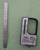
My apparatus consisted of a small FM-Radio antenna, which telescopes. The antenna was fixed to the handlebar clamp, and extending to touch the back of the windscreen at about mid height. When the bike is in motion, with wind pushing against the windscreen, the windscreen will flex backwards and cause a contraction of the antenna. I would ride up to speed, note the maximum speed, then come to a stop. A fine scale ruler would measure the resulting gap, which corresponds to how must the antenna was compressed.
A separate apparatus consisted of a fisherman's scale, used to measure the weight of fish. Inside my garage, I applied the fisherman's scale at the top edge of the windscreen, and pulled back horizontally. After applying a pre-determined force (10 lbs), I later observed how much the antenna compressed. The two points (force versus antenna location) were not coincident, but I could scale the lever-arm lengths to find the expected deflection at the top edge of the windscreen under that applied force.
OTHER SCREENS
Most screens are racked at 30-degrees off of vertical. This angle various a bit between manufacturers, but not by more than +/- 5 degrees. As such, these calculations are transferrable to other marketed screens.
Most screens have a similar horizontal curvature (as viewed from the sky, looking downwards). As such, the coefficient of drag would be similar amongst other marketed screens. The only exception is if a large NACA vent is featured on the windscreen.
My windscreen does not have a louver (laminar lip) above the upper lip of the windscreen. Other windscreens which do include a windscreen should not use these calculations, since the drag coefficient could be substantially different.
~~~~~~~~~~~~~~~~~~~~~~~~~~~~~~~~~~~~~~~~~~~~~~~
MY RESULTS
Dimensions of the after-market windscreen
9 in = Width along top edge
14 in = Width along top fastener row
13 in = Width along btm fastener row
14 in = Height from top fastener row to top screen
3 in = Height between top and btm row of fasteners
1 in = Height between btm row and btm edge of screen
Deflection and resulting pullout force from riding against wind
140 kph = Vehicle speed into static air.
3 mm = Horizontal deflection at antenna device
6 mm = Horizontal deflection at top of windscreen
13 lbs = Pullout force on each of two btm fasteners.
This
5 lbs = Horizontal pulling force between top edge of screen
13 lbs = Pullout force on each of two btm fasteners.
~~~~~~~~~~~~~~~~~~~~~~~~~~~~~~~~~~~~~~~~~~~~~~~
CONCLUSIONS
The above forces occur for steady wind at the noted vehicle speed. Gusted winds are approximately 40% higher pressure over the coincident steady winds. So, the calculations should be amplified by 40% higher to represent driving past a large truck.
Wind pressure scales to the square of the wind speed. Example:
100% = Steady pressure from vehicle speed at 140 kph (baseline)
150% = Steady pressure from vehicle speed at 170 kph
210% = Gusted pressure from vehicle speed at 170 kph
Applying a horizontal force of 5-lbs at the top edge of the windscreen, will result in a reaction of the two bottom fasteners to have the same pullout force (13-lbs each) as experienced when riding at 140 kph (steady wind). This same force would arise in 100 kph (steady wind) that is expected to gust to 140 kph.
Applying a horizontal force of 10-lbs (210%/100%) at the top edge of the windscreen, will correspond to the expected reaction forces of the two bottom fasteners experienced from gusting winds while riding at 170 kph (steady wind).
So, what speed should I test my screen for? Well, building's are designed to resist wind pressures with a factor of safety of (1.50 ~ 150%). If I validate that the windscreen can endure 150% higher pressure than expected, then an appropriate factor of safety has been incorporated. A test of 170 kph vehicle speed, would correspond to a safe operating speed of 140 kph, with wind gusting allowed for.
So, with my fish scale, I applied a force of 10-lbs at the top edge of the windscreen. Simultaneously I noted the status of the fasteners. The fasteners were not slipping - Good! This validated the installation of my fasteners to handle wind gusts that could arise while riding at 140 kph.
~~~~~~~~~~~~~~~~~~~~~~~~~~~~~~~~~~~~~~~~~~~~~~~
CONCERN
The after-market screen utilized the 'well-fasteners' that are fitted on the short Honda stock screen. These fasteners work by swelling up the rubber sleeve that surrounds the embedded nut behind the bike's mounting frame.
There has been much discussion on this forum elsewhere as to whether taller screens should not rely on these well-fasteners. Some riders have replaced the stock fasteners with steel nut-washer-bolt assemblies. There is also some caution expressed about the risk of over-tightening the fasteners, which might lead to cracking of the screen.
CALCULATIONS
As a practicing structural engineer, I endeavored to calculate (Excel and Mathcad) the wind pressures that could be expected on the windscreen at various speeds. I devised a rudimentary test to validate the calculations, where the one variable hardest to estimate would be the drag coefficient (Cd) of the screen.
TESTING
The same test could also be used to test the forces on the fasteners. I wanted to test the fasteners for excessive vehicle speed (above the speed limit), without actually exceeding the speed limit.
My apparatus consisted of a small FM-Radio antenna, which telescopes. The antenna was fixed to the handlebar clamp, and extending to touch the back of the windscreen at about mid height. When the bike is in motion, with wind pushing against the windscreen, the windscreen will flex backwards and cause a contraction of the antenna. I would ride up to speed, note the maximum speed, then come to a stop. A fine scale ruler would measure the resulting gap, which corresponds to how must the antenna was compressed.
A separate apparatus consisted of a fisherman's scale, used to measure the weight of fish. Inside my garage, I applied the fisherman's scale at the top edge of the windscreen, and pulled back horizontally. After applying a pre-determined force (10 lbs), I later observed how much the antenna compressed. The two points (force versus antenna location) were not coincident, but I could scale the lever-arm lengths to find the expected deflection at the top edge of the windscreen under that applied force.
OTHER SCREENS
Most screens are racked at 30-degrees off of vertical. This angle various a bit between manufacturers, but not by more than +/- 5 degrees. As such, these calculations are transferrable to other marketed screens.
Most screens have a similar horizontal curvature (as viewed from the sky, looking downwards). As such, the coefficient of drag would be similar amongst other marketed screens. The only exception is if a large NACA vent is featured on the windscreen.
My windscreen does not have a louver (laminar lip) above the upper lip of the windscreen. Other windscreens which do include a windscreen should not use these calculations, since the drag coefficient could be substantially different.
~~~~~~~~~~~~~~~~~~~~~~~~~~~~~~~~~~~~~~~~~~~~~~~
MY RESULTS
Dimensions of the after-market windscreen
9 in = Width along top edge
14 in = Width along top fastener row
13 in = Width along btm fastener row
14 in = Height from top fastener row to top screen
3 in = Height between top and btm row of fasteners
1 in = Height between btm row and btm edge of screen
Deflection and resulting pullout force from riding against wind
140 kph = Vehicle speed into static air.
3 mm = Horizontal deflection at antenna device
6 mm = Horizontal deflection at top of windscreen
13 lbs = Pullout force on each of two btm fasteners.
This
5 lbs = Horizontal pulling force between top edge of screen
13 lbs = Pullout force on each of two btm fasteners.
~~~~~~~~~~~~~~~~~~~~~~~~~~~~~~~~~~~~~~~~~~~~~~~
CONCLUSIONS
The above forces occur for steady wind at the noted vehicle speed. Gusted winds are approximately 40% higher pressure over the coincident steady winds. So, the calculations should be amplified by 40% higher to represent driving past a large truck.
Wind pressure scales to the square of the wind speed. Example:
100% = Steady pressure from vehicle speed at 140 kph (baseline)
150% = Steady pressure from vehicle speed at 170 kph
210% = Gusted pressure from vehicle speed at 170 kph
Applying a horizontal force of 5-lbs at the top edge of the windscreen, will result in a reaction of the two bottom fasteners to have the same pullout force (13-lbs each) as experienced when riding at 140 kph (steady wind). This same force would arise in 100 kph (steady wind) that is expected to gust to 140 kph.
Applying a horizontal force of 10-lbs (210%/100%) at the top edge of the windscreen, will correspond to the expected reaction forces of the two bottom fasteners experienced from gusting winds while riding at 170 kph (steady wind).
So, what speed should I test my screen for? Well, building's are designed to resist wind pressures with a factor of safety of (1.50 ~ 150%). If I validate that the windscreen can endure 150% higher pressure than expected, then an appropriate factor of safety has been incorporated. A test of 170 kph vehicle speed, would correspond to a safe operating speed of 140 kph, with wind gusting allowed for.
So, with my fish scale, I applied a force of 10-lbs at the top edge of the windscreen. Simultaneously I noted the status of the fasteners. The fasteners were not slipping - Good! This validated the installation of my fasteners to handle wind gusts that could arise while riding at 140 kph.
~~~~~~~~~~~~~~~~~~~~~~~~~~~~~~~~~~~~~~~~~~~~~~~
Attachments
Last edited:
")